Light Your Haunt With Hacked LED Christmas Lights
Overview:
Shove a bunch of LEDs into a can, then watch Ohm’s Law and Murphy’s Law duke it out.
Safely lighting our outdoor haunt has always been a compromise game. Every spotlight comes with an extension cord, and those routes have to be planned because haunt visitors are like free range chickens, or BBs. They run all over. Keeping the electrified snakes from attacking our chickens is a key responsibility that we don’t take lightly.
In an effort to reduce the snake population, we investigated other lighting options and came up with what seemed to be a viable alternative: Low voltage landscape lighting.
 Specifically, we built an assortment of LED spots, powered by a 12V 350W transformer over 12AWG low voltage power cable. Because the cable carries 12V DC current, it can be safely “tucked” an inch or so beneath the soil with just a spade.
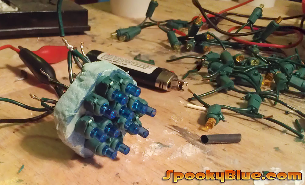
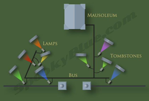
Each lamp consists of a cluster of LED Christmas lights housed in a length of two-inch diameter PVC pipe, which is sealed and mounted to a post. The positive and negative leads are attached with wire nuts to a low voltage wire connector. The best part of this arrangement is that the connector can be attached to the power bus at any point along its length, allowing for greater flexibility in the layout of our lighting plan.
With fewer extension cords lying about, there are fewer opportunities for “unplanned interactions” between them and our guests. All we had to do was keep our chickens from tripping over the lamps.
Theory
The basic idea is to pack as many LEDs as possible into the can without setting any fires. The not setting any fires part requires that we understand a few key concepts. For example, why would I wire three or four LEDs in series, and then connect three or four of these series circuits together in parallel? If you know the answer, then you can go outside and play while the rest of the class catches up.
It is usually at this point in a dissertation on LEDs that the author devotes several paragraphs to a review of Ohm’s Law. Instead of heading off into those weeds, we’re going to wade through some other weeds. We’ll tackle the math as we go.
How do LEDs work?
In the most general terms, a circuit is designed to operate at a particular voltage, and will draw as much current as it needs. An LED requires a certain minimal current to turn on. The “forward voltage” is the least amount of voltage required to allow current to flow through the LED. The amount of current changes (exponentially) based on the amount of voltage that is applied. A small increase in voltage results in a large increase in current. The more current, the brighter the light. That is, until it overheats and dies.
There are two species of LED Christmas lights. One type consists of red, orange, yellow, green, and blue LEDs. The other type utilizes only a white LED encased in a colored plastic sheath or bulb. It’s important to know the difference because the latter type provides a simpler solution for our application. All the LEDs have the same power requirement: About 2V(forward), and about 3V(optimal), drawing about 20mA. For simplicity’s sake we’ll be discussing this type of LED.
Note: I had a zillion of the colored LEDs and no data sheet, which meant I had to employ my unpaid assistants, Trial and Error, to determine the power requirements for each color. I should mention that Trial was generally cautious during testing while Error ham-handedly blew through not a few LEDs.
Think of voltage as a sluice gate above a water wheel.

Say the gate is marked with stops, 1-12, that represent voltage.
Open the gate to 1 and a trickle of water flows over the wheel, but it’s not enough to make it turn.


Open the gate to 3 and now there’s enough power to grind some corn.
We’re at optimal voltage and the LED glows at the brightness for which it was designed.

Wiring LEDs in series
 An LED is polarized, meaning it has a positive lead(anode) and a negative lead(cathode). To wire two LEDs in series, connect the positive side of one to the negative side of the other. Note: Always connect the anode to the positive side of the voltage source, and the cathode to the negative side of the voltage source.
How many LEDs can safely be connected in series? Simply add up the voltage requirement for each LED until you reach source voltage (12V in this case). Assuming 3V(20mA) for each LED, the answer is four (3V+3V+3V+3V=12V). This series circuit can handle 12V, and would draw 20mA.
I can’t get my LEDs to add up to exactly 12V
Three goes into 12 four times, which is nice. But suppose your LEDs can’t handle 3V, and instead prefer 2.5V. In that case, how do you get to an even number of LEDs?
- Option I – Intentionally overload the circuit
You can place 5 LEDs in series. Each LED would get 2.4V (12V / 5 = 2.4V), instead of 2.5V, which means they’ll be a little dimmer. But it might not be enough of a difference for you to notice. Then again, they might be a lot dimmer, in which case you’re on to your second option. - Option II – Use a resistor to drop excess voltage
 Place four LEDs in series. Since these four LEDs would only require 10V (2.5V * 4 = 10V), you need to drop the extra two volts with a resistor. The resistor value can be calculated with Ohm’s Law as R = V / I. If each LED requires 20mA (.02A), then the resistor value would be 100Ω. (2V / .02A = 100Ω) So, you would add a 100Ω resistor at one end of your series circuit to deal with that extra two volts.
 - Option III – Overdrive the circuit
Don’t. You saw what happened to the miller.

Wiring LEDs in parallel
Four LED Christmas lights don’t emit much light, and we’ve determined that we can’t add more LEDs to our series circuit, so how do we pack more light into our lamp? Simple. Build four series circuits, then wire those together in parallel.
 At the end of each series circuit is a lead. One is positive, the other is negative. Connect the positive leads, connect the negative leads, and you now have a cluster. Each series circuit draws 20mA, so the cluster would draw a total of 80mA.
How many series circuits can be wired together in parallel to form a cluster? That depends on how much current your power supply can provide, and how good you are at packing everything together inside its container. Our 12V transformer is rated at 350W. To figure the total amount of current I can draw from the transformer, [I(Amps) = P(Watts) / V(Volts)] Therefore, 350W/12V = 29A, or 29,000mA.
Our transformer could, theoretically, provide current for roughly 362 clusters (80mA * 362 = 28,960mA). That’s assuming, of course, that our power bus is a superconductor, or a spherical chicken in a vacuum. It’s neither, so voltage losses in the power cable would probably be a limiting factor. Still, you could pile on a lot of lamps without worrying about the transformer bursting into flames.
Coming up…
How to build a 12V LED lamp.
I know what you’re thinking. We’re two articles into this project (if you count the introduction), and we haven’t yet glued anything to the workbench (silicone sealant is surprisingly adhesive) or accidentally hurled a hunk of PVC across the room (off the table saw, and I’m extremely lucky to still have two ears).
I figured it was a good idea to cover the more arcane aspects of the project first. With these out of the way, the rest of the construction is a snap.