
12V Haunt Lighting with Hacked LED Christmas Lights
I think the secret to a successful blog is to write only about five articles a year. Your traffic, if you ever had any, will fall through the floor, and that really takes the pressure off.
This makes perfect sense to anyone who has ever been labeled a curmudgeon. If it doesn’t describe you, however, then my definition of “successful” is almost certainly different from yours, in which case you should probably just ignore that first bit altogether.
If you’re just joining the party, we are transforming LED Christmas lights into a 12V haunt lighting system. In part I, we touched on the genesis of this project. Part II covered some LED basics, and in this third and final part, we tackle the wiring, lamp construction, and a few other bits that should be helpful if you decide to build your own LED haunt lights.
 Prep the wire

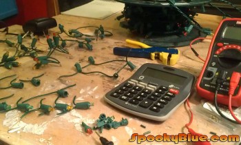
You’ll need at least one spool of LED Christmas lights that you don’t mind destroying. It’s easier to work in sections, so unspool about four feet and snip all three wires.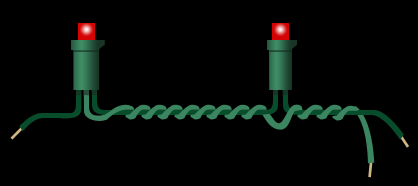 Yes, there are three wires, and you’ll notice the middle wire connects every nth LED. Snip this middle wire about an inch from every LED to which it is connected, then unravel these longer wires and set them aside. They will come in handy later. You’ll have a pretty good pile of extra wire before long, so toss the pieces into a shoe box, or a bucket.
Separate the LEDs
You should now have a strand of LEDs on a single wire. Separate them by snipping the wire halfway between each LED. When you’re finished, you’ll have a small stockpile of LEDs, most with two leads, and a handful with three leads. Trim the leads so they’re all the same length and strip about 1/2″ of insulation from the ends. Repeat until you get bored.
Mark the LED polarity
 As we discussed in Part II, LEDs are polarized. Current will only flow through an LED when the negative lead is connected to the negative side of the voltage source. You’ll need to identify the positive and negative sides. There are several ways to do this.
- Test for continuity with a multi-meter to see which direction current flows.
- Remove the LED from its plastic casing and look for a flat side, or notch, which indicates the cathode (negative).
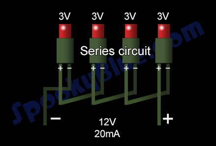
- Apply 3V and see if it lights up. If not, reverse the leads. A universal power supply is invaluable for testing LEDs. You can also tape two AA batteries together (positive to negative) to get three volts. Do NOT use a 9V battery without adding a 300? resistor in series to drop the extra 6V. (Ohm’s Law states: 6V / 20mA = 300?) Note: LEDs run on magic smoke; let it out and they quit working. Applying three times the voltage at which an LED is rated will usually do the trick.
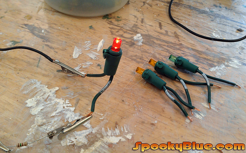
What about the lights with three wires sticking out of them? The third wire is connected to one side or the other (+ or -), which means you’ll have two negatives, or two positives. Pick one and snip it close to the base. Problem solved.
Once you’ve determined the polarity of your leads, mark one of them. I marked all my positives with a silver Sharpie. If you’re lucky, the plastic casing will have a clip, or some other mark, that is always on the same side. If so, then use this as a clue to mark the other leads; it’s not necessary to check polarity on the rest of the LEDs.
Build the cans
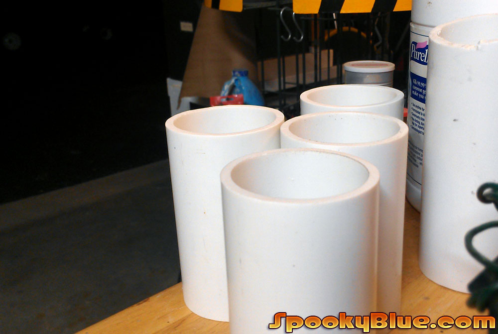 For our cans, we chose 2″ PVC pipe, cut into lengths of about six inches. If you are adept at making straight cuts with a hacksaw (I’m not), then this will be a snap. If you have a large ratcheting pipe cutter (I don’t – yet), then even better. If you decide to cut your PVC using a table saw (I did), then I can’t stress enough the importance of observing every safety precaution you ever heard of, up to, and including, wearing a lacrosse helmet over a hockey mask. See exhibit A below, which illustrates the effects of “kick-back”, and very nearly compromised the bilateral symmetry of my face.

Cutting PVC pipe with a table saw is like fishing with dynamite. In fact, I take it all back; don’t do this. It’s dangerous, it will prematurely wear down your saw blade, eat puppies, and make you sterile. But … if you’re willing to take a chance with your life, then build a wooden jig to firmly hold the pipe in place, use a fine-toothed blade, cut in warm weather to reduce the chance of splintering, and wear gloves and face protection. Or maybe try a chop saw. Hmm. Why didn’t I just use the chop saw?
Assemble the lamp
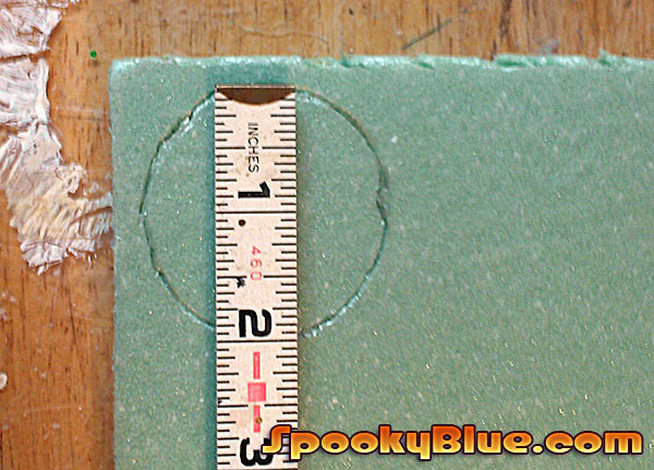
 A bit of 1/2″ foam board makes a decent substrate to keep the LEDs from rattling around. Cut a disk to the same inner diameter as the can (two inches, in our case). You want a snug fit, but if it’s too tight, then sand lightly around the outside of the disk.
Your disk need not be an exact circle, but it’s generally preferable that the substrate conform to the shape of the container in some fashion (cough).
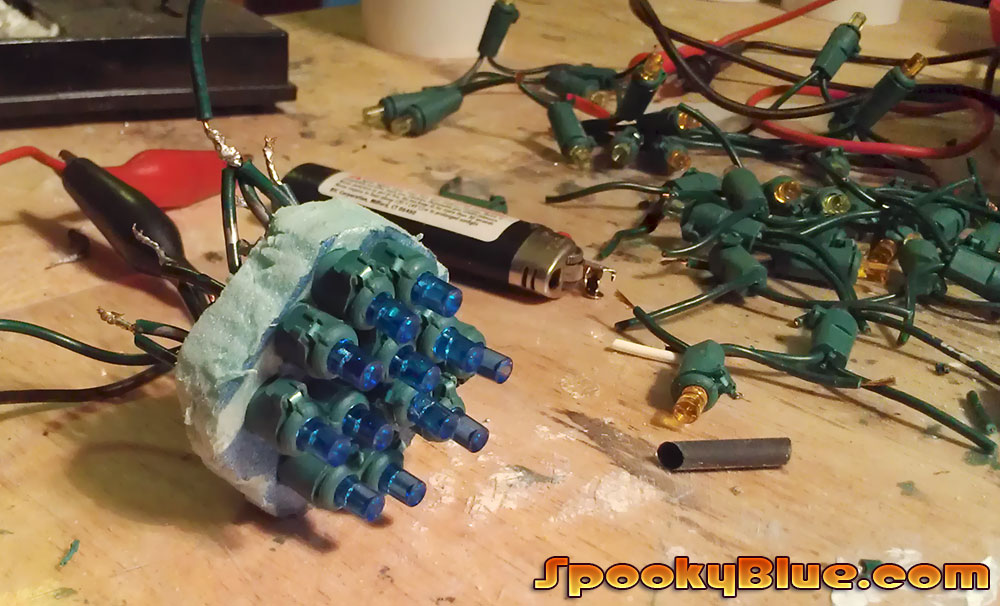
To insert an LED, first poke a hole through the disk with a nail, then open the hole with a small circular file. A cordless drill would probably speed things up (he said, wondering about his fixation with small circular files). Make the hole a bit smaller than the LED case so it fits snugly, and insert each LED so the positive leads are facing the same direction.
If you sorted your LEDs by color, then you probably have five separate piles of red, green, blue, amber, and yellow. These can be combined to produce new colors. Trying out different combinations is a fun way to waste a lot of time.
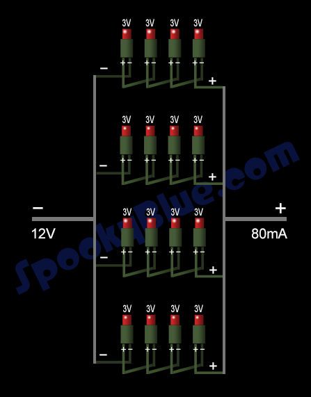
 This drawing of a spiky Christmas ornament is, in fact, the wiring diagram for a 16-LED lamp.
It consists of four columns of four LEDs, each wired in series. At the end of each series circuit is a positive and a negative lead. These are connected to form a parallel circuit. See our previous article in this series for a more in-depth discussion of this horoscopy.
Note, in this first photo, how difficult it becomes to determine the polarity of the LEDs when one has not properly marked the leads. Additionally, planning your wiring routes ahead of time, and inserting your LEDs all in the proper direction, will avoid the need for any “bridge” wires (cough hack).
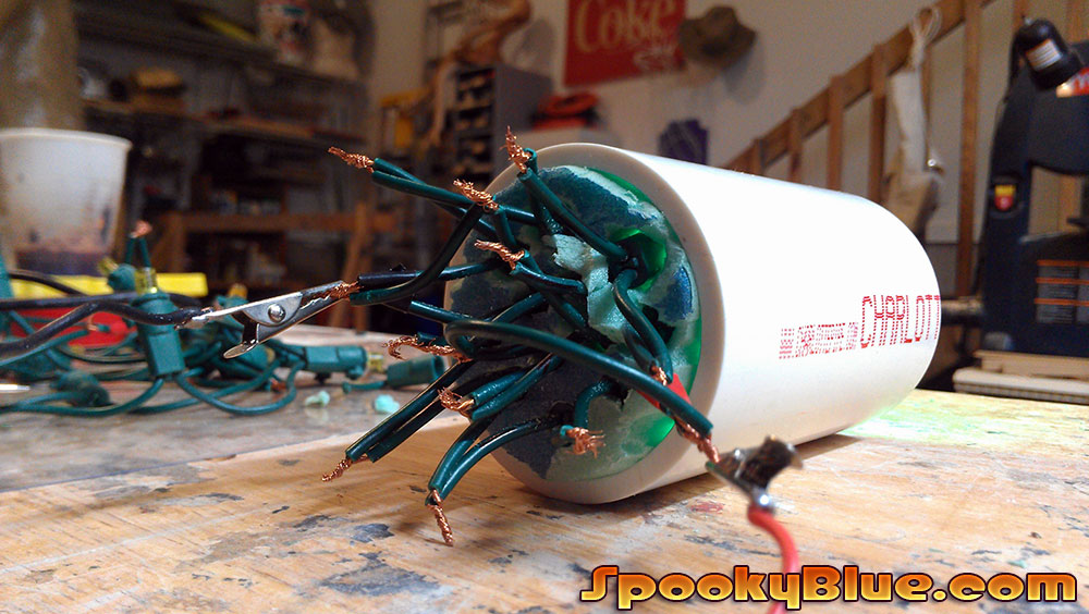
 Attach a long wire (from your bucket-o-wire) to the positive and negative leads of the assembled lamp, marking one of the leads outside the can (my positives are marked with red electrical tape), then connect to 12V to make sure everything works. After soldering all connections, it’s not a bad idea to wrap them in electrical tape to prevent any shorts. This would probably not be necessary if you cut your leads shorter. Apply some carpenter’s glue around the edge of the disk and slide the assembly into the can far enough that everything except the two long lead wires are fully inside the can.
Build the post

A two inch vertical beam (1x2x2) is attached to a four inch length of 1×2 lumber with two 1″ wood screws, forming a “T”. This is mounted to the can with two 1.25″ hex bolts. Drill holes for the mounting bolts through the wall of the can on either side of the lamp assembly.
Drill a hole through the base of the “T” large enough to accept a 1/4×1″ bolt (overkill, but I had a box of 1/4″ wing nuts). A washer and wing nut hold everything in place. Simply loosen the wing nut to adjust the angle of the lamp.
Seal the can
PVC end caps come in several varieties, from a $0.40 plastic insert, to a $3.00 end cover. However, for one whose list of quirks includes saving bits of plastic and other refuse in bins in one’s garage because “this might come in handy”, there are other options, especially if one is fond of a particular brand of grape jelly.
Drill a hole through the center of the cap and feed the wires through. If you use metal as a cover, insert a strain relief bushing, or rubber grommet, to protect the insulation from sharp metal edges. Apply a bead of caulk, or silicone sealant, around the inside of the cap and press firmly.
 Our lens, a 2″ diameter disk cut from plastic sheeting (typically used in vacuum forming), is held in place with a 2″ PVC coupler and a bead of caulk. Any clear plastic would work just as well.
Why not just glue the end and lens cap using PVC cement? Because history teaches there’s a better than average chance we’ll need to get back inside this thing at some point in the future.
Hook it up
 Place your 12V transformer in a (protected, waterproof) central location and run your cabling. Two-conductor cable is ridged on one side. Attach the ridged side to the positive lead of the transformer.
Attach a low voltage wire connector to the leads on the back of your lamp, taking care to note which side of the connector is positive. Place the positive side of the connector over the ridged side of the cable and firmly press the ends together. Metal prongs inside the connector pierce the cable jacket to make the electrical connection.
Weeds
 Part of the fun of any new project is answering the question, “I wonder if this will work.” Okay, that’s not a question, but the answer is yes, if your expectations are low enough.
Okay, that’s not an answer. Let me put it another way. My expectations weren’t altogether realistic at the start of this project. Shadow Wood is located in a very dark hollow where ambient light is practically nil, and I prefer more illumination than these little guys alone can provide.
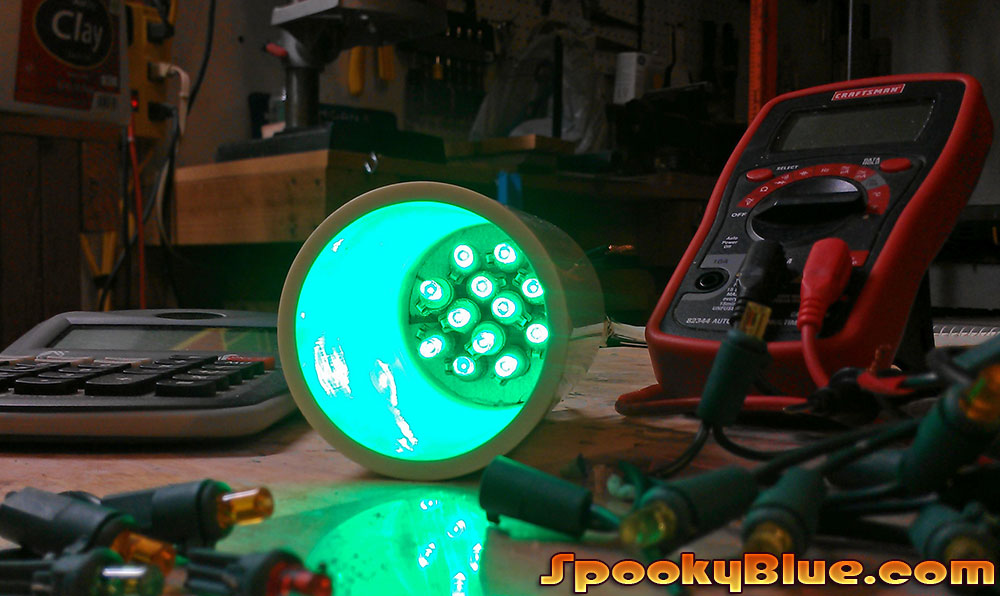
As accent lighting, however, the lamps work very well. We placed 12 throughout Shadow Wood, and once I got it into my head that their job was to provide little pools of color, I was happier with the outcome. Change your attitude, change your life. (gah…yes, yes, I know. Hypocrite, hypocrite, hypocrite)
 The takeaway here is that 12 little LED Christmas light lamps won’t illuminate your cemetery like a honking 110V halogen flood. But they nicely fill a niche and only tap a small percentage of what the transformer can provide. Namely, nice steady current, which is exactly what high power (1W, 3W) LEDs enjoy most. Aha!
 Which brings us to why this project is probably a bad idea. Now, I suppose you can make the case that you could burn down your garage with a soldering iron, a definite consideration. And, of course, there’s the possibility that a flying bit of PVC shrapnel could make your sunglasses sit crooked for the rest of your life. But these are just hazards we face every day. The real problem here is weeds.
Specifically, it’s the heading-off-into part that’s the trouble. There’s untapped potential in this project, both literally and figuratively. For instance, what will it take to make honest to gawd floods out of 3W LEDs? (Off into the weeds) With easy access to 12V DC, what other work can I make it do for me? (More weeds. Always more weeds)


